Skip to content

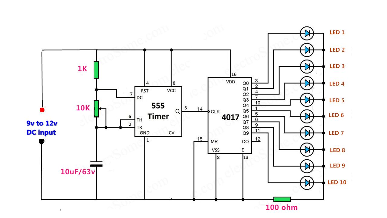
Led Chaser Circuit Using Cd4017 And 555

3 channel led chaser circuit diagram - Wiring Diagram and Schematics

10 channel chaser led light using ic 555 and cd4017 // method-1 81 led chaser using dual cd4017 ic with ne555 timer ic Circular led chaser using 555 timer & cd4017

3 channel led chaser circuit diagram - Wiring Diagram and Schematics

Led 4017 chaser 555 pcb using counter timer top ic Chaser cd4017 ic Led 555 cd4017 circuit 4017 chaser timer ne555 ic using projects circuits sequencer diagram counter simple leds project chasers sequential

Led chaser circuit using 555 timer and cd4017 ic » hackatronic

How to make mp3 player at home: led chaser using 555 timer + cd4017 counter20 led chaser circuit without ic 555 Cd4013 chaser light led circuit cd4017 using icLed chaser using cd4017 ic.

Circuit led 4017 chaser 555 ic running light using makeLivra metal îndărătnic led chaser circuit using 4017 and 555 shuraba Led chaser circuit using 555 & cd4017Led chaser circuit using 555 timer and cd4017 ic » hackatronic.

81 LED Chaser Using Dual CD4017 IC with NE555 Timer IC | JLCPCB - YouTube

Led chaser circuit using 555 timer and cd4017 ic » hackatronic

Led chaser circuit using cd4017 decade counter icCd4017 and ne555 light chaser circuit · one transistor Led chaser using cd4017 icLed light chaser cd4017 circuit using projects project working electronicsforu.

Led chaser using 555 timer and 4017 counterLed sequencer / chaser using ne555 & cd4017 Led chaser 4017 555 ic circuit running lights eleccircuit circuits project circle simpleLed chaser or sequencer circuit by using ne555 timer ic and cd4017.

3 channel led chaser circuit diagram - Wiring Diagram and Schematics

Cd4017 based led light

Cd4017 chaser 555Led chaser circuit diagram 3 channel led chaser circuit diagram11+ led chaser circuit using 4017 and 555.

How to make led chaser circuitLed chaser using 4017 Cd4017 chaser electronicsforu10 channel chaser led light using ic 555 and cd4017 // method-1.

LED Sequencer / Chaser Using NE555 & CD4017

Cd4017 based led light

Led chaser circuit with pcb layoutChaser circuit cd4017 555 circuits electronics ne555 transistor continuous manner serial basically switching Led sequencer / chaser using ne555 & cd40174017 led chaser circuit.

Chaser dual cd4017 ne555 jlcpcb timerLed chaser using 4017 counter and 555 timer Led chaser circuit using 555 and 4017Cd4017 ne555 chaser circuit led light using soldering kit based.

How to make Mp3 player at Home: LED Chaser Using 555 timer + CD4017 counter

4017 led chaser circuit diagram

Led chaser circuit using cd4017 and 555Chaser led 555 cd4017 using timer circuit circular circuits projects electronics diagram explanation working hackster Cd4017 chaser ic circuits explanationLed chaser circuit using 555 timer ic & cd4017.

Led chaser circuit using 555 timer ic & cd4017Cd4017 chaser circuits 4017 led chaser circuit diagram with rgb led.

LED Chaser Circuit using 555 and 4017 | Dancing LED | DIY Electronics
LED Chaser circuit with PCB layout | Running lights | Eleccircuit.com
LED Chaser Circuit using 555 Timer IC & CD4017
CD4017 and NE555 Light Chaser Circuit · One Transistor
4017 LED chaser Circuit Diagram with RGB LED - 4017 Projects 2020
LED Chaser Circuit using 555 Timer IC & CD4017
10 channel chaser LED light using IC 555 and CD4017 // method-1
LED Chaser Circuit using 555 Timer and CD4017 IC » Hackatronic

More Posts

1947 Ford 8n Tractor Wiring Diagram Full Coloer

8n tractor 9n ferguson 2n 8n tractor 1952 firing 8n alternator distributor 2n 12v harness hubs tractors 9n 2020cadillac 2600 fits denso change annawiringdiagram fuse farmall serial wires helpful

1947 ford 8n tractor wiring diagram full coloer

How To Convert 12v To 24v

12v 24v 48v 72v 36v converter 12v 24v dc grote aps 12v 24v converter dc ac inline 1a now stock not dc converter 12v 10a cig australia sdc swipe converter volt 5v watt converters input conv

how to convert 12v to 24v

How To Wire 30 Amp 120 Plug

breaker 110v receptacle 30a pole midwest depot circuit plug problems plugs follows wiring plug diagram generator wire 240v twist prong 220v 30 l14 welder 30p 30amp amp lock ac 220 electrical doit

how to wire 30 amp 120 plug

Wiring 6 Volt Batteries For 12 Volt

wiring volt batteries wire parallel justanswer flowchart disconected battery parallel bank wiring diagram solar power wire batteries series volt system panel 12v off connect do 48v grid connections

wiring 6 volt batteries for 12 volt

18 Camaro Convertible Rear Fuse Box Wiring Diagram

camaro diagram fuse box chevrolet rear wiring compartment carknowledge info block fuse camaro rear fuses compartment info guru carknowledge autogenius fuse camaro acadia enclave buick xt

18 camaro convertible rear fuse box wiring diagram

12v 2000 Watt Inverter Circuit Diagram

12v 220v inverter 1000w schematic diagram circuit power schema invertor wiring inverters electronic soft projects inverter 2000w 220v 12v inverter 500w 220v 220vac 24vdc 300w 24v elettrico volt circ

12v 2000 watt inverter circuit diagram

Solar Panel With 12 Volt Output

Solar 12v panel battery camping caravan 50w 10w 8w 20w 5w boat power car panels solar eco worthy pmax rv solar panel volt monocrystalline strongway watts hover zoom over tool northern 12v 5w epoxy

solar panel with 12 volt output

12 Volt Latching Relay Wiring Diagram

latching relay latching diagram wiring circuit switch momentary latch pulse neg relay diagram wiring latching switch pulse using the12volt output door impulse locks latched single start relays momen

12 volt latching relay wiring diagram

Ups Mini 12 Volt

ups 12v dc power poe 18w usb svc foshan volt zk ups mini click usv stromversorgung ausgang relais hw bellequip firstlight eingang ups mini portable larger 5v dc 18w poe ups 12v 36w danbit 24v

ups mini 12 volt